Biogas from anaerobic digestion can be used as engine fuel after treatment to meet the selected engine’s requirements. Potential sources include livestock manure, food waste, agricultural residues and wastewater sludge. Gas from different processes varies in methane content, moisture and contaminants, so the source alone does not establish suitability.
A project assessment should compare the site’s hourly gas production with its electricity demand. Where gas production varies, the operating plan may require reduced electrical output, scheduled operation, gas storage or multiple smaller generator sets.
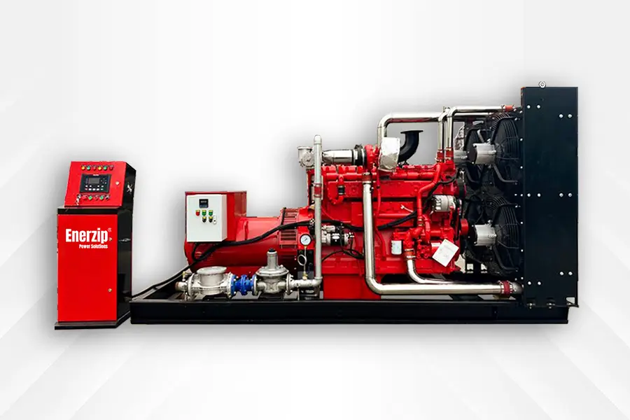
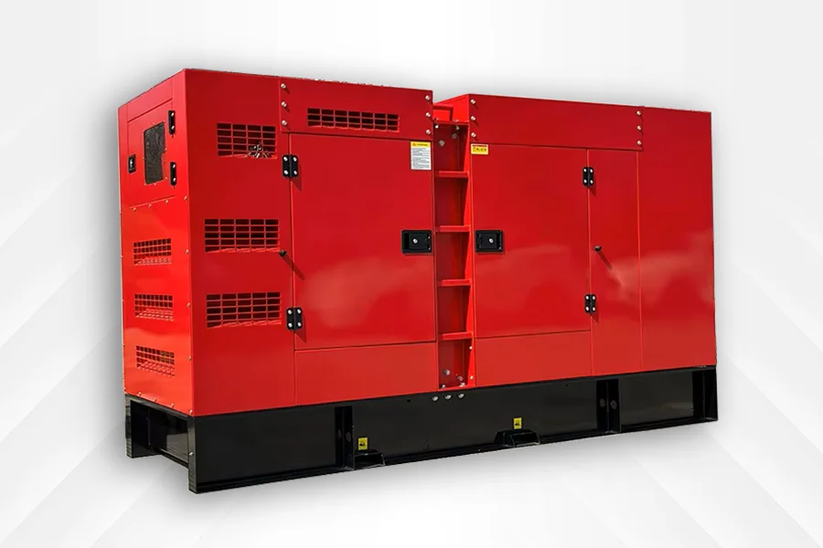
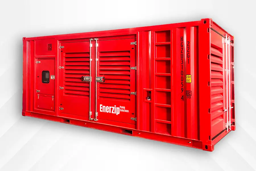
ENERZIP Biogas Generator Specifications
The following table lists the supplied catalogue configurations. Electrical voltage, frequency, power factor, applicable operating duty and site output must be confirmed in the quotation and final technical datasheet.
| Genset Model |
ESP (kVA) |
ESP (kW) |
PRP (kVA) |
PRP (kW) |
Gas Consumption (Nm³/h, 100% / 75% Load) |
Open-Type Dimensions L × W × H (mm) |
Silent-Type Dimensions L × W × H (mm) / Container |
Engine Model |
Country of Origin* |
Cylinder Arrangement |
Displacement (L) |
Governor |
Cooling |
| C20G5B |
22 |
16.5 |
20 |
15 |
19.0 / 15.0 |
1400 × 800 × 1040 |
2680 × 1100 × 1732 |
4B3.9-NG |
China |
L4 |
3.9 |
E |
Water Cooling |
| C25G5B |
27.5 |
22 |
25 |
20 |
21.0 / 16.0 |
1400 × 800 × 1040 |
2680 × 1100 × 1732 |
4B3.9-NG |
China |
L4 |
3.9 |
E |
Water Cooling |
| C30G5B |
33 |
27.5 |
30 |
25 |
22.0 / 17.0 |
1560 × 800 × 1100 |
2680 × 1100 × 1732 |
4BT3.9-NG |
China |
L4 |
3.9 |
E |
Water Cooling |
| C35G5B |
41.25 |
33 |
37.5 |
30 |
24.0 / 18.0 |
1560 × 800 × 1100 |
2680 × 1100 × 1732 |
4BT3.9-NG |
China |
L4 |
3.9 |
E |
Water Cooling |
| C40G5B |
48.125 |
38.5 |
43.75 |
35 |
25.0 / 19.0 |
1610 × 800 × 1100 |
2680 × 1100 × 1732 |
4BT3.9-NG |
China |
L4 |
3.9 |
E |
Water Cooling |
| C50G5B |
55 |
44 |
50 |
40 |
27.0 / 21.0 |
1610 × 800 × 1100 |
2680 × 1100 × 1732 |
4BTA3.9-NG |
China |
L4 |
3.9 |
E |
Water Cooling |
| C60G5B |
68.75 |
55 |
62.5 |
50 |
36.0 / 28.0 |
1930 × 880 × 1240 |
2680 × 1100 × 1732 |
6B5.9-NG |
China |
L6 |
5.9 |
E |
Water Cooling |
| C70G5B |
79.75 |
66 |
72.5 |
60 |
50.0 / 38.0 |
1930 × 880 × 1240 |
2680 × 1100 × 1732 |
6BT5.9-NG |
China |
L6 |
5.9 |
E |
Water Cooling |
| C100G5B |
110 |
88 |
100 |
80 |
58.0 / 45.0 |
2000 × 930 × 1240 |
3170 × 1150 × 1780 |
6BTAA5.9-NG |
China |
L6 |
5.9 |
ECM |
Water Cooling |
| C125G5B |
137.5 |
110 |
125 |
100 |
65.0 / 49.0 |
2350 × 970 × 1450 |
3820 × 1190 × 2062 |
6CT8.3-G1-NG |
China |
L6 |
8.3 |
E |
Water Cooling |
| C150G5B |
165 |
132 |
150 |
120 |
75.0 / 58.0 |
2350 × 970 × 1450 |
3820 × 1190 × 2062 |
6CTA8.3-NG |
China |
L6 |
8.3 |
E |
Water Cooling |
| C200GB |
220 |
165 |
200 |
150 |
92.0 / 70.0 |
2800 × 1050 × 1600 |
3970 × 1270 × 2222 |
6LTAA8.9-NG |
China |
L6 |
8.9 |
E |
Water Cooling |
| C250G5B |
275 |
220 |
250 |
200 |
120.0 / 90.0 |
2900 × 1050 × 1600 |
3970 × 1270 × 2222 |
NTA855-NG |
China |
L6 |
14 |
E |
Water Cooling |
| C300G5B |
330 |
275 |
300 |
250 |
180.0 / 140.0 |
2930 × 1050 × 1800 |
4215 × 1400 × 2250 |
KTA19-NG |
China |
L6 |
19 |
E |
Water Cooling |
| C375G5B |
412.5 |
330 |
375 |
300 |
205.0 / 160.0 |
2930 × 1050 × 1800 |
4215 × 1400 × 2250 |
KTA19-NG |
China |
L6 |
19 |
E |
Water Cooling |
| C625G5B |
678.5 |
550 |
625 |
500 |
300.0 / 230.0 |
3850 × 1600 × 2180 |
4615 × 1850 × 2530 |
KTA38-NG |
China |
V12 |
38 |
E |
Water Cooling |
| C1250G5B |
1375 |
1100 |
1250 |
1000 |
560.0 / 430.0 |
4320 × 2000 × 2400 |
ISO 20 ft Container |
QSK60G |
China |
V16 |
60 |
ECM |
Water Cooling |
| C1500G5B |
1650 |
1320 |
1500 |
1200 |
650.0 / 500.0 |
4760 × 2100 × 2410 |
ISO 20 ft Container |
QSV81 |
China |
V16 |
81.6 |
ECM |
Water Cooling |
| C1875G5B |
2062.5 |
1650 |
1875 |
1500 |
820.0 / 630.0 |
5290 × 2100 × 2660 |
ISO 40 ft Container |
QSV91 |
China |
V18 |
91.6 |
ECM |
Water Cooling |
Technical notes: PRP = prime power; ESP = emergency standby power; E = electronic governing; ECM = electronic control module. L indicates an inline cylinder arrangement, and V indicates a V arrangement.
The table retains the supplied catalogue values. The kVA/kW pairs for C20G5B, C30G5B, C70G5B, C200GB and C300G5B do not correspond to a power factor of 0.8. The C625G5B standby pair also requires confirmation. Final electrical ratings and the applicable power factor must therefore be confirmed before equipment selection.
Gas consumption figures are references pending confirmation of methane content, lower heating value, normal-volume conditions and load basis. They are not guaranteed consumption figures for untreated site gas. Country-of-origin entries are reproduced from the catalogue and do not independently establish the engine’s manufacturing origin. Engine manufacturer, origin, fuel specification and final enclosure dimensions are to be identified in the project documentation.
Gas Analysis and Generator Sizing
Generator capacity should be based on the usable gas available at the engine inlet. A daily production total is useful for an initial assessment, but hourly production records provide a better basis for selecting equipment and planning operation.
The gas analysis should identify methane, carbon dioxide, oxygen and nitrogen, together with hydrogen sulphide, moisture and other relevant contaminants. Siloxanes should be assessed where the feedstock or process presents a risk, particularly in wastewater and some waste-treatment applications.
Electrical output depends on both gas quantity and fuel quality. A lower methane concentration reduces the energy available per unit volume. Engine suitability and any resulting output limitation must be checked against the selected engine’s fuel specification.
Gas Treatment Requirements
The treatment system must bring the gas within the engine manufacturer’s limits. Depending on the raw gas, this may require hydrogen sulphide removal, drying, condensate separation, filtration and siloxane treatment. A universal contaminant limit should not be applied across all engine models.
Gas pressure and flow must remain within the specified range during operation. Pipe losses, filter pressure drop and changes in demand should be considered when selecting any gas blower or pressure-control equipment.
The supply scope must identify responsibility for gas treatment, storage, blowers, the engine gas train, isolation equipment and site pipework. These items are included only where stated in the quotation.
Operation with Variable Gas Production
Biogas production can change with feedstock, digester temperature and process conditions. The control strategy should account for these changes without operating the engine outside its permitted load and fuel-pressure limits.
Where required, the project can be assessed for load reduction, controlled shutdown, scheduled operation or multiple-generator operation. The relevant gas-pressure signals, storage-level signals and plant control interfaces must be defined during engineering.
Generator-to-generator parallel operation requires compatible governing, excitation and protection systems. Exporting electricity to the utility network requires a separate connection design and approval process.
Heat Recovery Options
Engine cooling water and exhaust contain heat that may be recoverable for digester heating, process water or other suitable thermal loads. The useful heat output depends on the generator load, engine configuration and required supply and return temperatures.
A heat recovery proposal should specify the heat exchangers, pumps, controls and connection points. The design must maintain the engine’s cooling and exhaust limits and provide a means of rejecting heat when the site does not require it.
Installation and Maintenance
The installation layout should provide access for routine servicing and component removal. Ventilation, exhaust discharge, condensate handling, electrical protection and earthing must be designed for the site. Gas detection, emergency isolation and their control interfaces should be defined as part of the installation design.
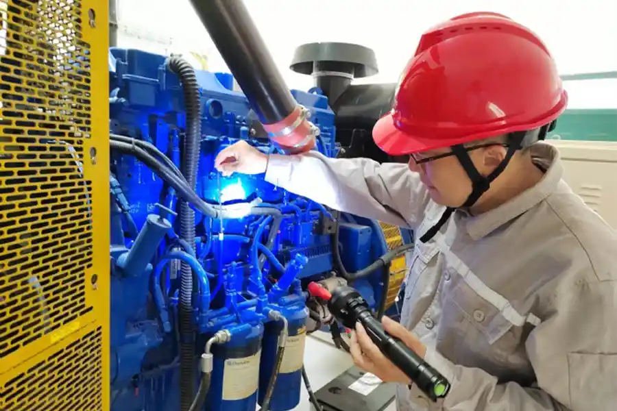
Maintenance follows the selected engine manufacturer’s instructions and the actual operating conditions. Fuel contaminants can affect lubricating oil, ignition components and engine deposits. Gas sampling and oil analysis, where specified, help establish suitable inspection and service intervals.
Commissioning should verify gas quality and inlet pressure, cooling operation, electrical output, alarms, shutdowns and the agreed control functions. Load testing and acceptance criteria must be stated in the project scope.
Frequently Asked Questions
How much biogas is needed to operate a generator?
The required flow depends on methane content, heating value, generator efficiency and operating load. Provide the minimum, average and maximum hourly gas production, together with a recent gas analysis. Daily production alone may conceal periods when insufficient gas is available.
What gas test results should I provide?
Provide methane, carbon dioxide, oxygen, nitrogen, hydrogen sulphide, moisture or dew point, and lower heating value. Include siloxanes and other contaminants relevant to the feedstock. State the sampling location and whether the sample was taken before or after treatment.
Does the biogas need desulphurization and drying?
Treatment is required whenever the raw gas exceeds the selected engine’s fuel limits. Digester gas commonly requires moisture management and may require hydrogen sulphide removal. The treatment equipment must be selected from measured inlet conditions and the required outlet quality.
What happens when gas production is insufficient?
The operating strategy may reduce electrical load or stop the generator before gas conditions move outside the engine’s limits. Gas storage or multiple smaller units may help accommodate production changes, subject to the project design.
Can heat from the generator be used to warm a digester?
Heat recovery can be assessed for this purpose. Provide the digester’s heating demand, required water temperatures and operating schedule. The recoverable heat and equipment scope must be calculated for the selected engine and expected electrical load.
What maintenance does a biogas generator require?
Routine work includes the engine manufacturer’s specified oil and filter changes, ignition-system checks, cooling-system inspection and other scheduled tasks. Gas treatment equipment also requires servicing. Maintenance intervals depend on operating hours, fuel quality, oil condition and the engine’s instructions.